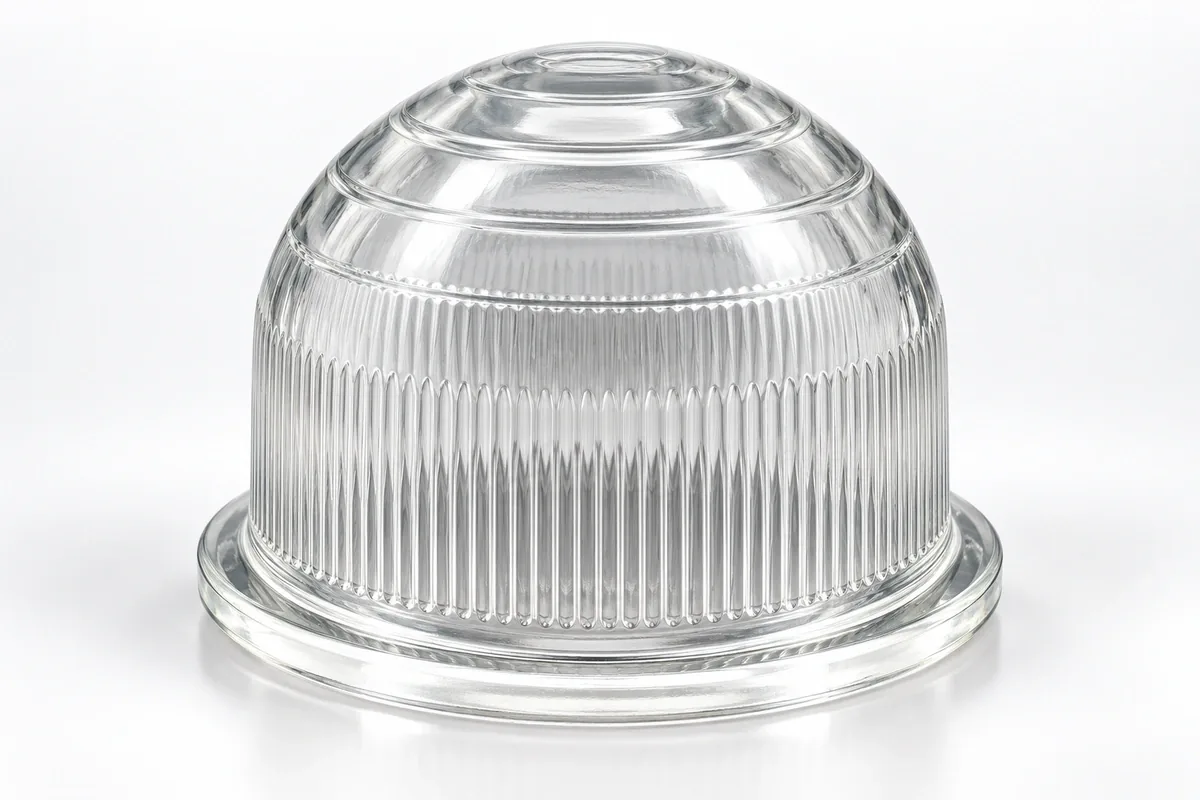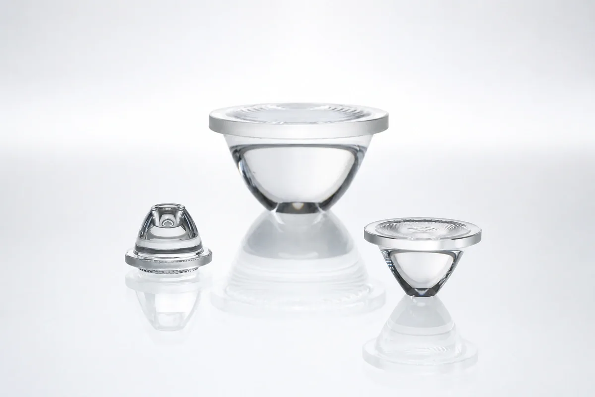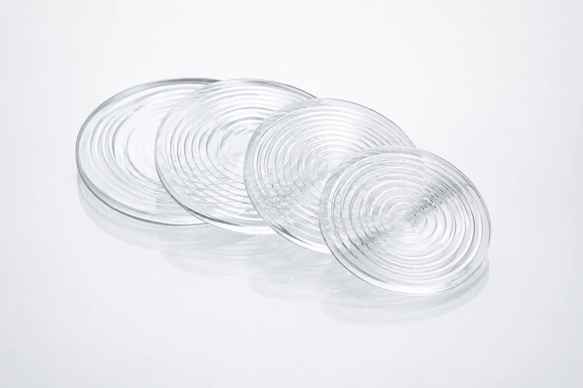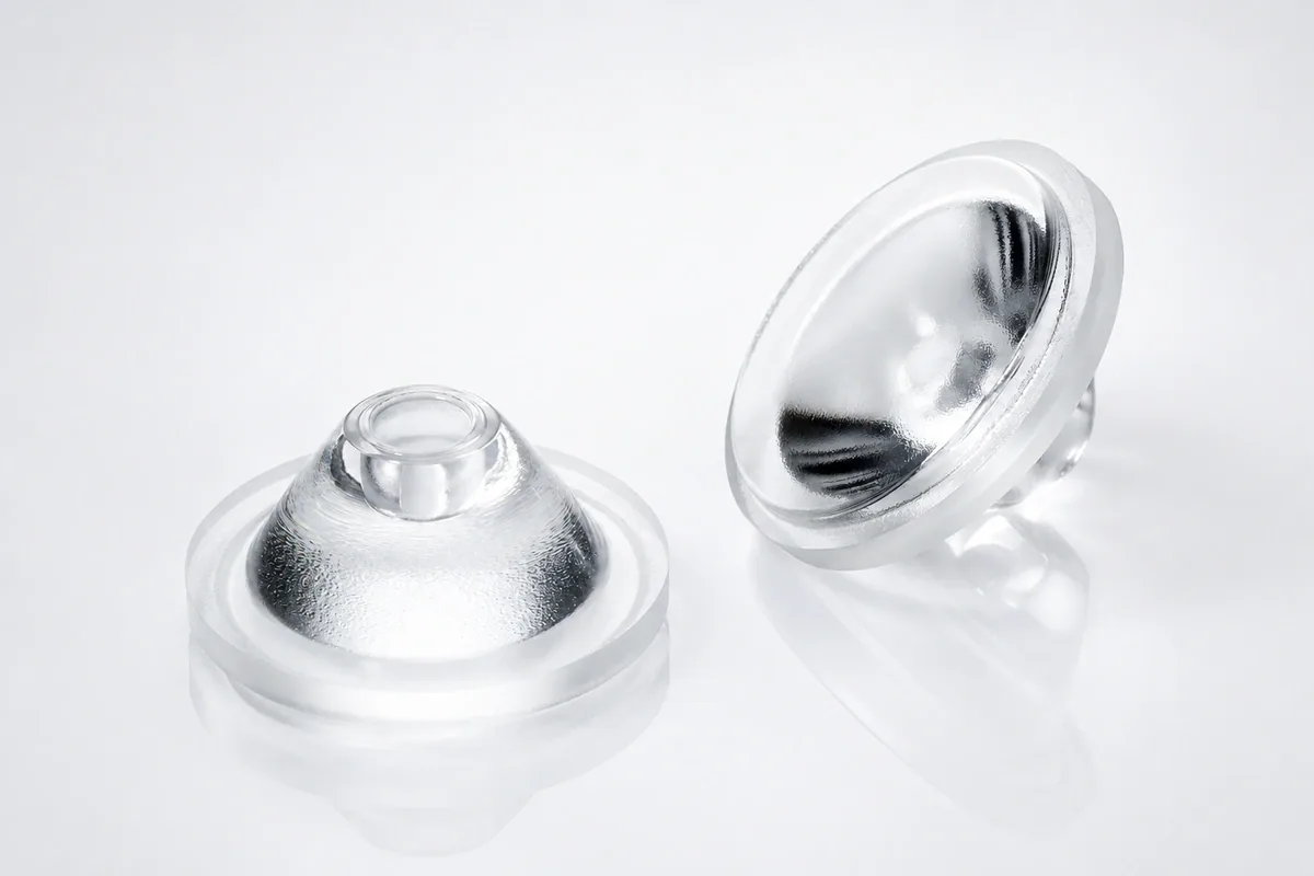
Custom Freeform Glass Lenses
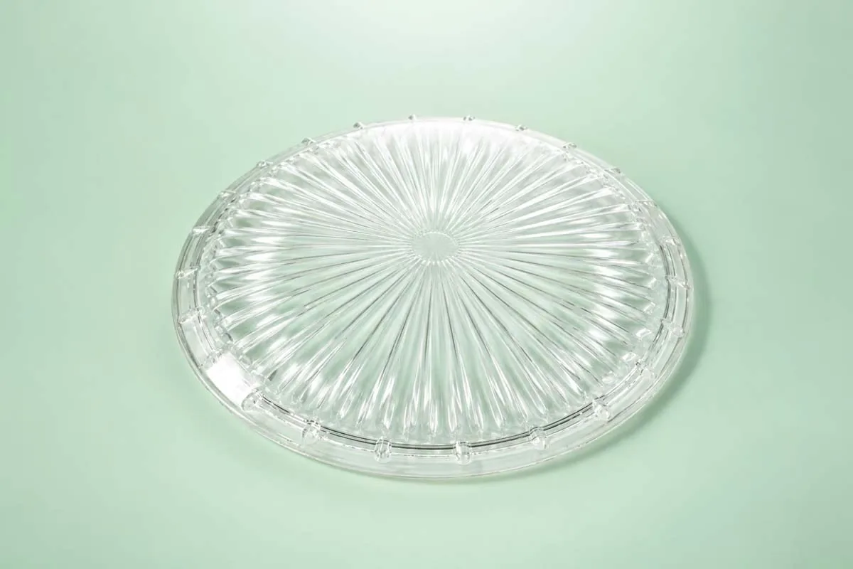
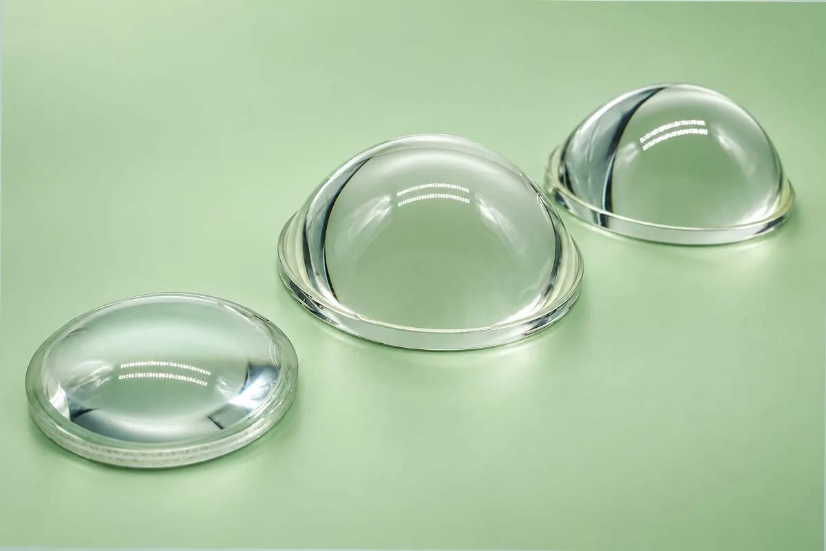
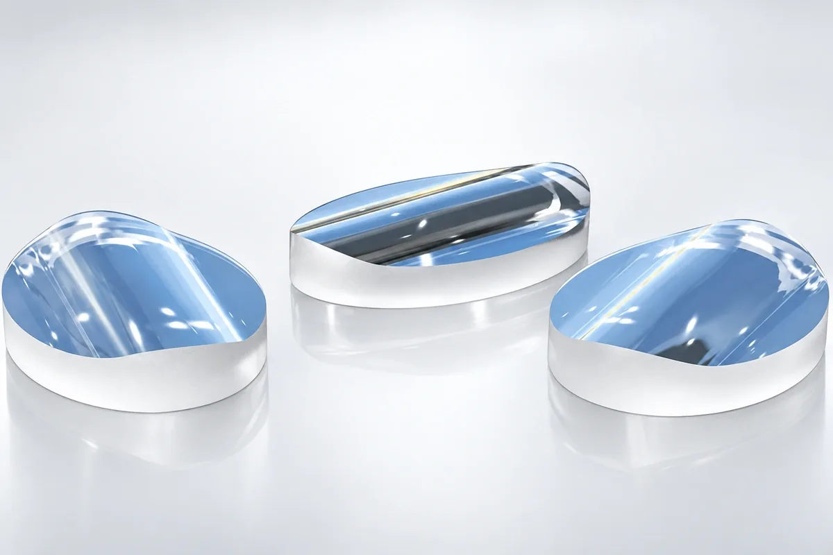
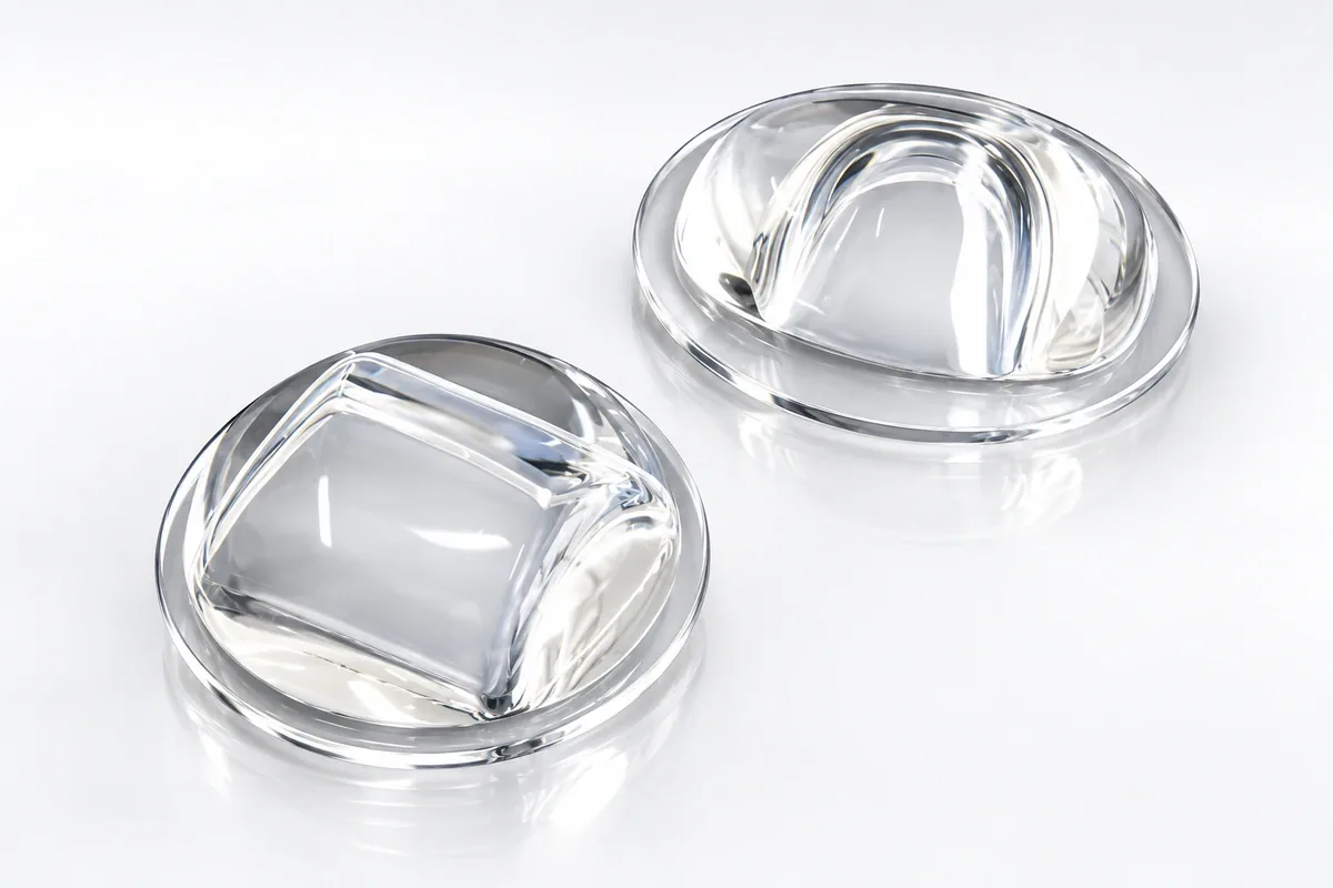
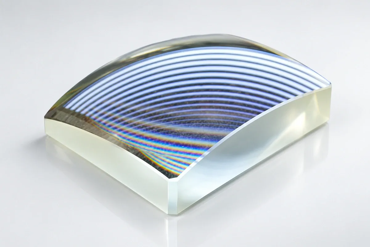
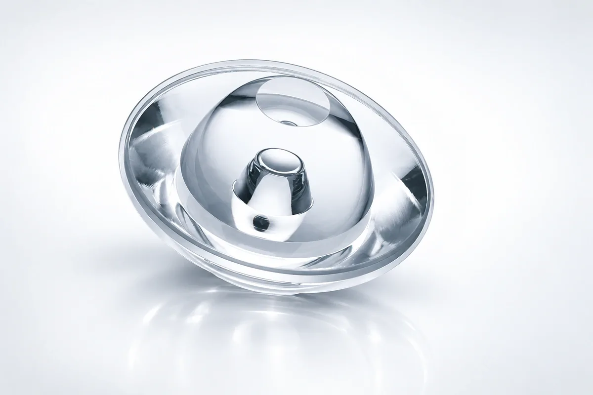
Freeform glass lenses use non-rotationally symmetric optical surfaces to place light where the application needs it. They can produce rectangular, oval, asymmetric, cutoff or otherwise shaped distributions that are difficult to obtain from a simple spherical lens.
The lens design is inseparable from the source and target. China Lampoptics therefore treats the emitter model, source position, intensity target, surface file and mechanical datums as one controlled design package.
Specification note: Numerical ranges shown on this page are preliminary engineering references for project screening. The quotation and approved drawing define the final material, dimensions, tolerances, processing route and inspection method.
Freeform Beam Distributions
| Distribution | Main characteristic | Typical use |
|---|---|---|
| Rectangular field | Places light within a defined width and height | Area, facade and machine lighting |
| Oval beam | Wide horizontal and narrow vertical spread or the reverse | Corridors, beacons and wall washing |
| Asymmetric roadway beam | Projects light forward and laterally from the pole | Street and perimeter lighting |
| Cutoff distribution | Limits light above or outside a controlled boundary | Architectural, vehicle and task lighting |
| Multi-zone distribution | Allocates different intensity to defined target regions | Specialty and signal lighting |
Optical Design Inputs
| Emitter model and emitting area | Specified production source, package revision and LES |
|---|---|
| Source angular distribution | Defined by the optical system and controlled acceptance target |
| Spectrum / wavelength | Defined by the optical system and controlled acceptance target |
| Source position and tolerance | Defined by the optical system and controlled acceptance target |
| Target plane / surface | Defined in the controlled optical model |
| Working distance | Defined in the controlled optical model |
| Target intensity or illuminance map | Controlled simulation or photometric target file |
| Efficiency / spill-light limit | Defined by the application acceptance specification |
| Obstructions and package envelope | Made to the approved drawing; production limit confirmed after tooling review |
| Simulation revision | Confirmed after drawing, sample and process review |
A label such as wide or asymmetric is not sufficient for a freeform design. The target must define where intensity is required, where it is restricted and at what distance or surface it is evaluated.
Surface and Mechanical Data
| Surface representation | Controlled CAD, point cloud, polynomial or NURBS file |
|---|---|
| Coordinate origin and axes | Explicitly defined in the controlled model |
| Clocking direction | Defined by the mechanical drawing |
| Clear aperture | Made to the approved drawing; production limit confirmed after tooling review |
| Outside envelope | Made to the approved drawing; production limit confirmed after tooling review |
| Seat / flange / locating feature | Defined by the mechanical drawing |
| Glass grade | Selected for the application and confirmed with the quotation and material data |
| Surface-form tolerance | Acceptance requirement stated on the drawing; achievable level confirmed after process review |
| Edge and draft requirements | Confirmed after drawing, sample and process review |
The optical coordinate system must be tied to physical datums. Without a controlled clocking feature, an asymmetric lens can be dimensionally correct but installed in the wrong orientation.
Tooling and Acceptance Planning
Lampoptics develops optical molds and production tooling in its mold workshop, then forms and anneals the glass before dimensional and functional evaluation. Coating can be added where the spectral and surface requirements justify it.
Freeform sag, envelope, glass grade, form tolerance and performance-verification responsibility are confirmed after the optical model is reviewed.
Freeform Glass Lens Processing
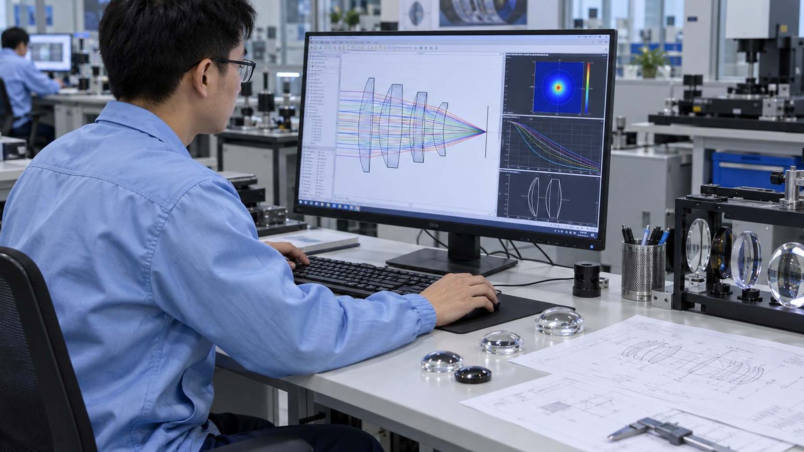
Optical Model Review
Source model, target distribution, freeform surface file, datum system and working distance are checked together.
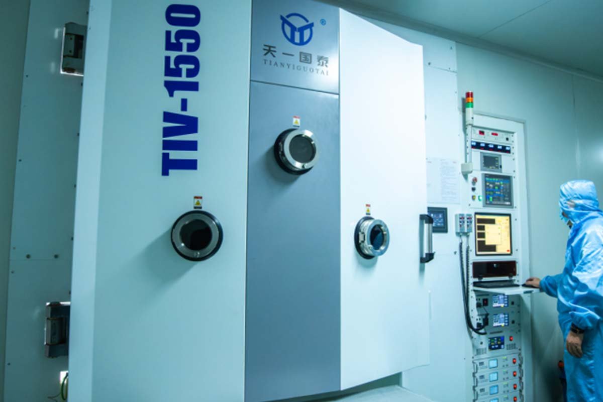
Freeform Tooling
The non-rotational optical surface and its mounting references are transferred into precision tooling.

Controlled Glass Molding
The freeform surface is replicated while controlling fill, shrinkage, alignment and residual stress.
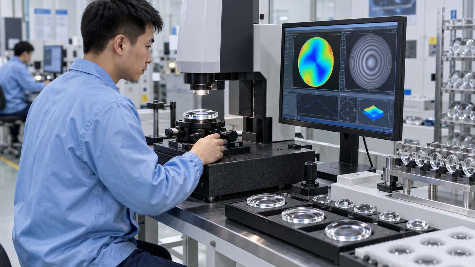
Performance Comparison
The molded lens is evaluated for dimensions, source registration and the required asymmetric beam distribution.
Applications
- Street and area lighting: forward and asymmetric distributions
- Vehicle warning and signal lights: oval, cutoff and directional beams
- Wall washing and corridor lighting: wide horizontal fields
- Architectural lighting: rectangular and controlled-edge illumination
- Industrial task lighting: light placed around machinery and work zones
Freeform Glass Lens FAQs
What makes a lens freeform?
Its optical surface is not limited to rotational symmetry and is optimized for a specific source and target distribution.
Can one design be used with another LED?
Changing emitting area, package height or angular output can change the distribution; the design must be rechecked.
What file formats are accepted?
A controlled CAD model is preferred. Point, polynomial or NURBS data can be reviewed, with the accepted transfer format confirmed before tooling starts.
How is clocking controlled?
A flat, notch, tab, hole or other datum relates the asymmetric optical surface to the holder.
How is a freeform lens approved?
Compare measured photometric data with the target and simulation using the defined source, position, drive condition and test geometry.