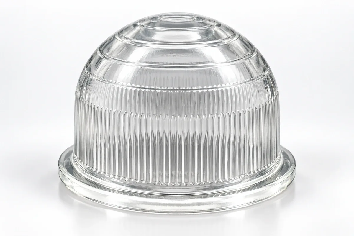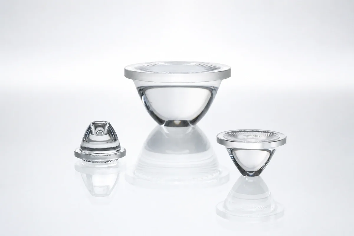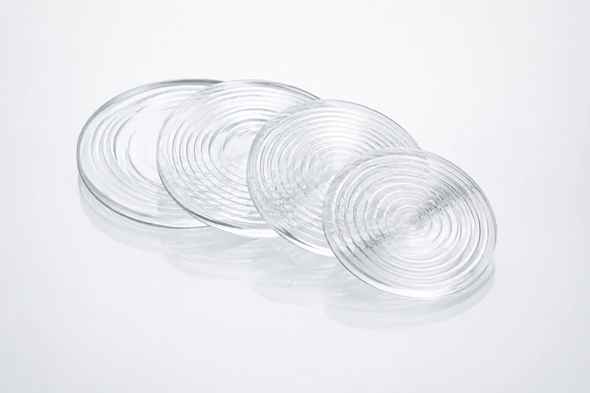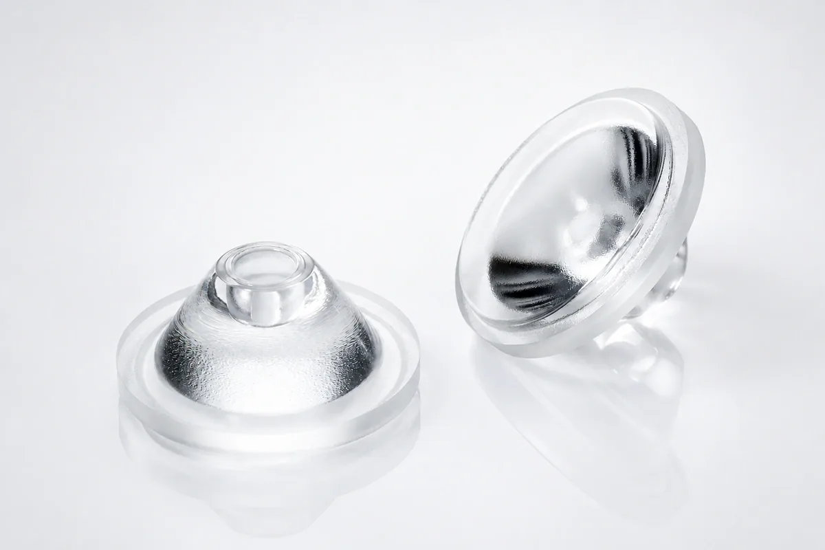
Custom Aspherical Glass Lenses
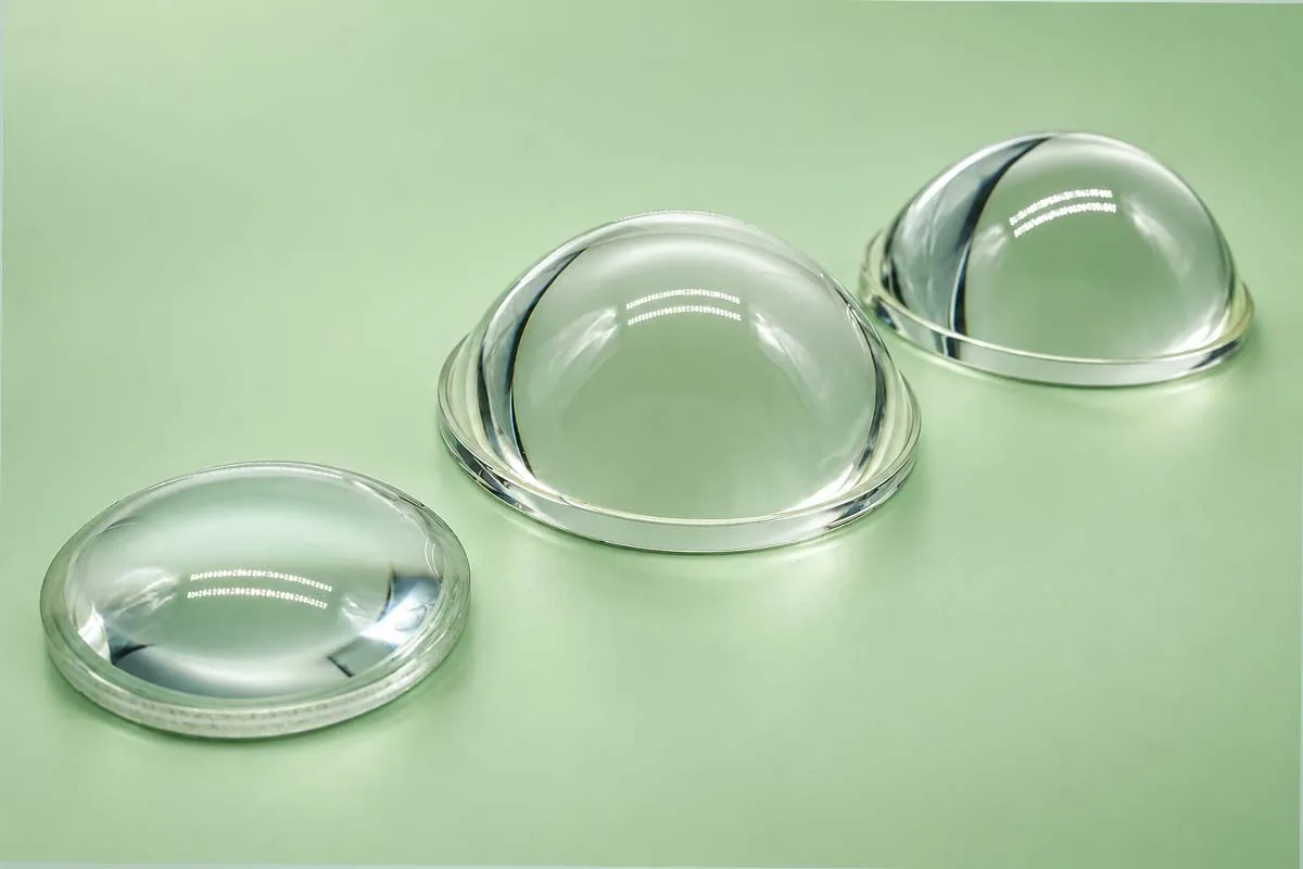
An aspherical glass lens uses a surface whose curvature changes from center to edge. The additional degrees of freedom can reduce spherical aberration, improve collimation or create a required illumination distribution with fewer optical elements than a comparable all-spherical system.
China Lampoptics develops molded aspheres for lighting and optical assemblies. The surface equation, sign convention, glass index, mechanical datum and clear aperture must be released together.
Specification note: Numerical ranges shown on this page are preliminary engineering references for project screening. The quotation and approved drawing define the final material, dimensions, tolerances, processing route and inspection method.
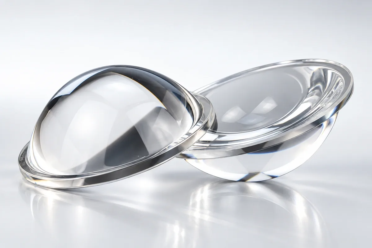
Aspherical Lens Forms
| Form | Description | Typical function |
|---|---|---|
| Plano-aspheric | One flat face and one aspheric face | LED collimation and compact focusing |
| Aspheric condenser | High-aperture positive lens | Light collection for stage and projection systems |
| Bi-aspheric | Two non-spherical optical surfaces | Compact multi-function optical correction |
| Flanged asphere | Optical body with an integrated mounting seat | Repeatable source-to-lens positioning |
| Freeform-aspheric hybrid | Rotationally asymmetric or locally optimized surface | Application-specific beam shaping |
Aspheric Surface Data
| Base radius | Defined in the released aspheric prescription |
|---|---|
| Conic constant | Defined in the released aspheric prescription |
| Polynomial coefficients | Controlled coefficient set |
| Coefficient convention and units | Explicitly stated in the controlled optical file |
| Surface sign convention | Explicitly stated in the controlled optical file |
| Optical origin and axis | Defined by the optical-to-mechanical datum scheme |
| Clear aperture | Initial feasibility screening uses the Ø1.5–120 mm molded-asphere reference envelope |
| Excluded edge zone | Defined in the released optical drawing |
An asphere cannot be reproduced from a nominal focal length alone. The complete equation or verified point data are required, including the coefficient convention and coordinate origin.
Optical and Mechanical Specifications
| Glass grade / refractive index | Selected for the application and confirmed with the quotation and material data |
|---|---|
| Design wavelength | Defined in the released optical prescription |
| Surface-form error | Reference target PV 0.1–3.5 µm; prescription and measurement method must be stated |
| Centration / wedge | Reference centration range 10 arcsec–5 arcmin; definition must match the inspection method |
| Effective focal length | Defined by the released optical prescription; feasibility confirmed during tooling review |
| Outside diameter / seat | Made to the approved drawing; production limit confirmed after tooling review |
| Center / edge thickness | Prescription-controlled; reference CT tolerance ±0.01–0.05 mm |
| Surface quality | Reference levels S/D 20-10 to 40-20; final zones are drawing-controlled |
| Transmission / coating | Target defined by the application or approved sample; achievable result confirmed during review |
The optical axis must be related to the outside diameter, flange, notch or other mounting datum. This relationship controls performance after the lens is installed.
Fused Silica Asphere Development
Fused-silica aspheric lenses are suited to UV-LED optics, laser delivery, exposure systems and selected semiconductor-equipment assemblies. The aspheric prescription is matched to the design wavelength, numerical aperture, clear aperture and mechanical mounting features.
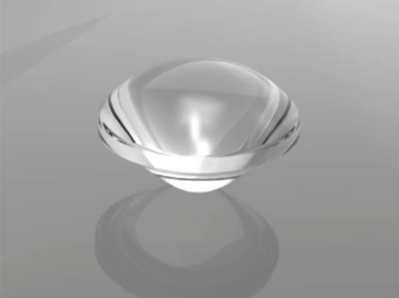
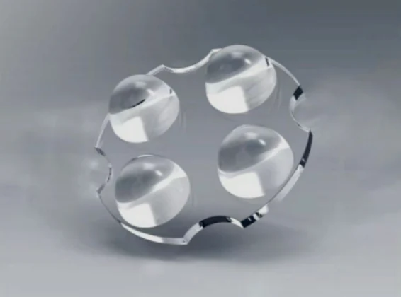
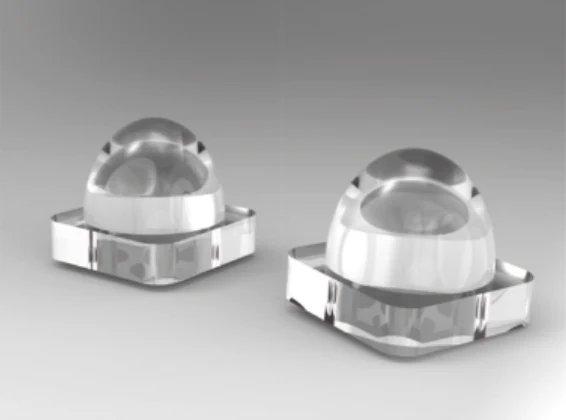
| Material | High-purity fused silica / silica glass |
|---|---|
| Refractive index | 1.46345 at 486 nm |
| Thermal expansion coefficient | 5.8 × 10⁻⁷ K−1 |
| Development inputs | Optical prescription, wavelength, clear aperture, mechanical seat, surface requirement and acceptance method |
Custom aspheric designs specify diameter, focal length, center thickness and surface tolerances on the optical drawing. The lens prescription and mounting dimensions are reviewed together.
Mold Development and Process Review
Lampoptics combines an optical-lens workshop with in-house mold development and controlled annealing. Precision molding is appropriate when the aspheric surface and its mounting geometry must be repeated in production.
Asphere diameter, sag, glass grade, form tolerance and measurement method are confirmed after prescription and tooling review. Project-specific coating can then be evaluated.
Aspherical Glass Lens Processing
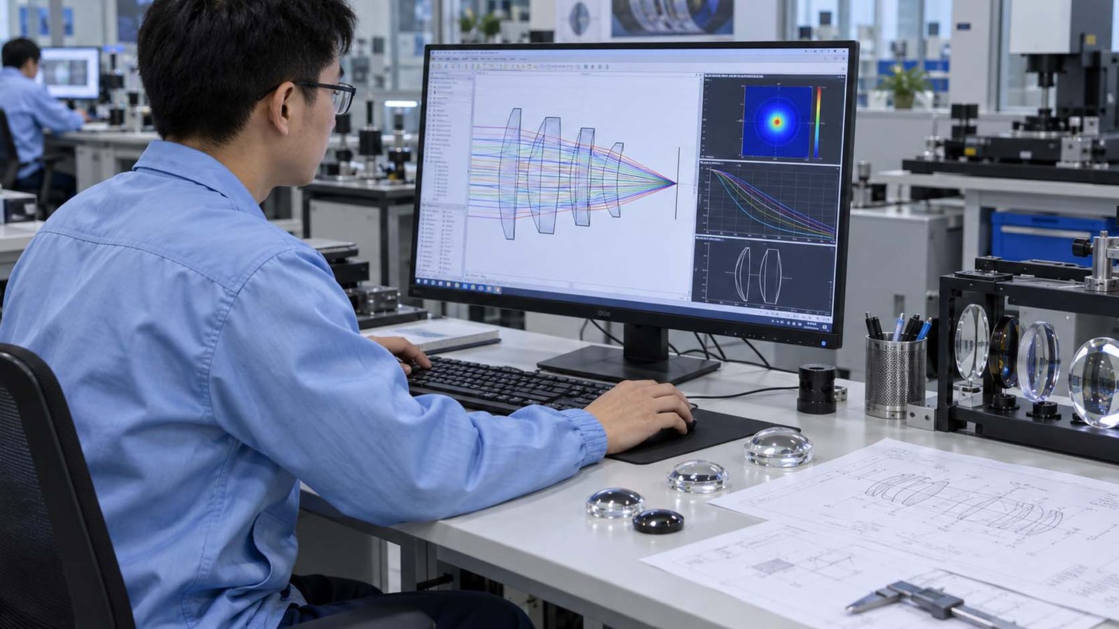
Aspheric Prescription Review
The sag equation, coefficients, clear aperture, reference axis and mechanical datums are confirmed.
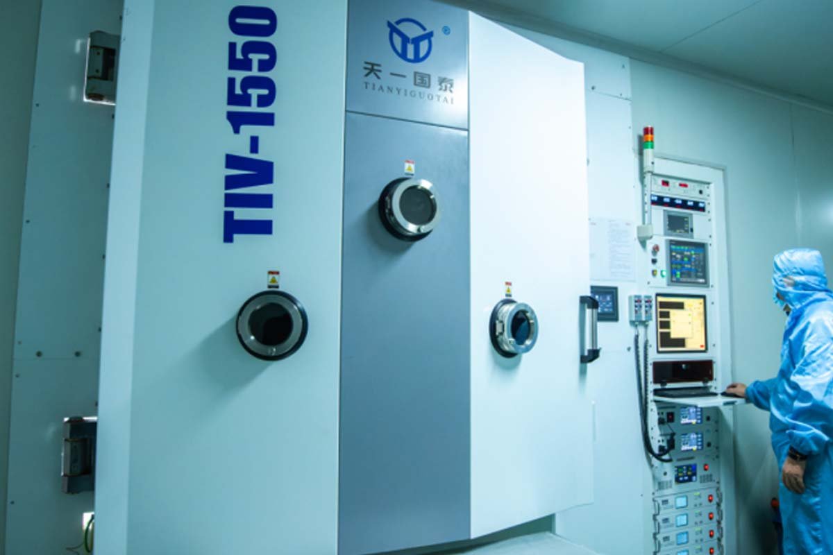
Precision Aspheric Tooling
The non-spherical optical surface is produced in the mold with the required form and surface finish.

Glass Molding and Annealing
The aspheric profile is replicated under controlled temperature, pressure and cooling conditions.
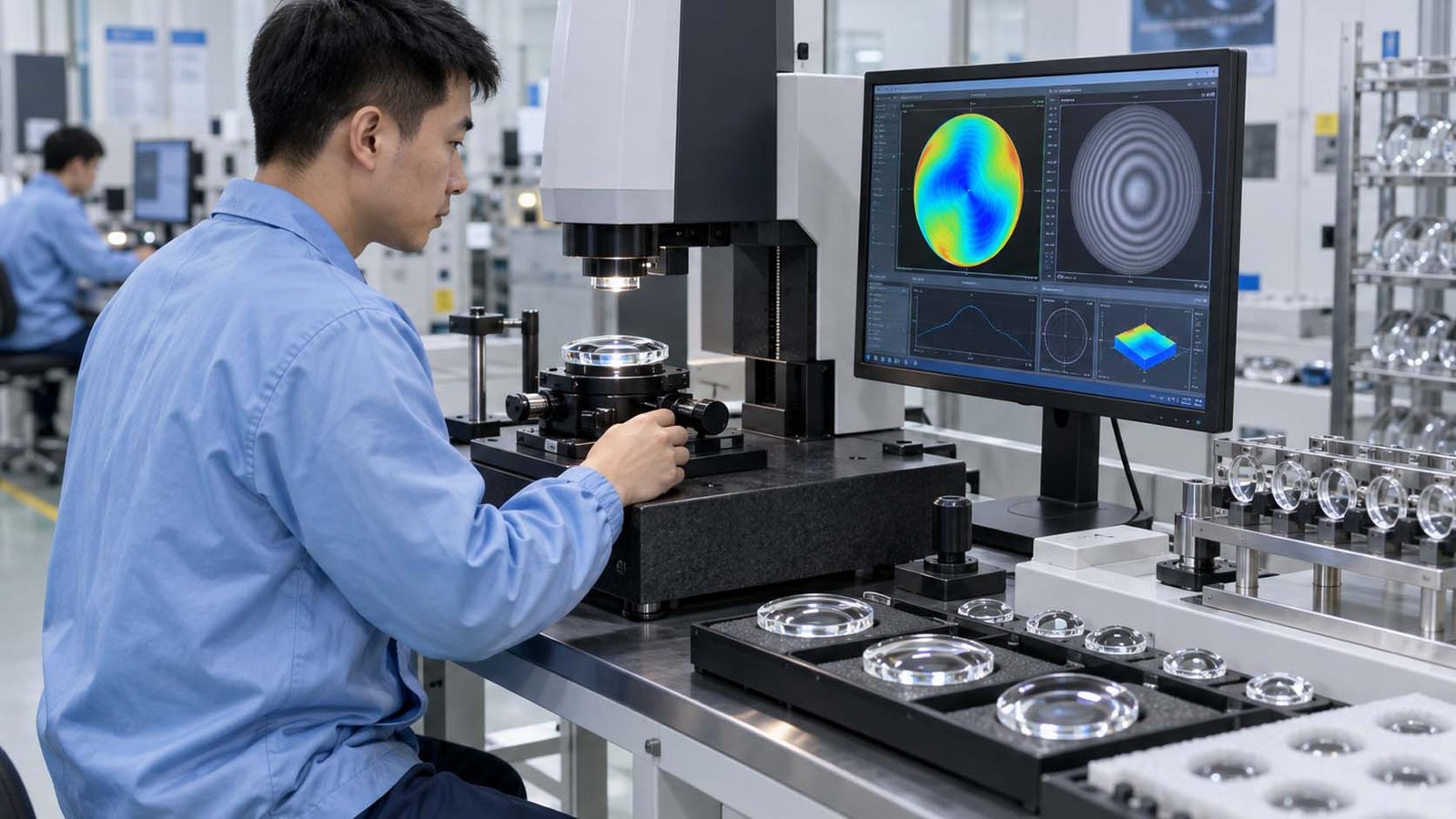
Form and Optical Inspection
Surface form, centration, focal performance, dimensions and cosmetic quality are verified to the approved plan.
Applications
- LED collimation: compact collection and beam formation
- Automotive and motorcycle lighting: headlamp, fog-lamp and signal optics
- Stage and projection lighting: high-aperture condenser systems
- Sensors and instruments: compact focusing and aberration control
- Industrial illumination: efficient source collection in heat-exposed assemblies
Aspherical Glass Lens FAQs
How is an aspheric lens different from a spherical lens?
Its curvature changes according to a defined equation rather than remaining part of one sphere.
What design file is required?
Provide the full aspheric prescription or controlled point data plus the mechanical drawing and glass definition.
Can an asphere include a mounting flange?
Yes. A flange or seat can be molded with the optic when the datum relationship and mold release are feasible.
How is surface form measured?
The measurement method and responsible party are agreed from the required form tolerance; no specific metrology equipment is claimed without confirmation.
Can Lampoptics copy an existing asphere?
Reverse engineering is possible only when surface measurement is combined with focal or beam validation; sample comparison alone is not sufficient.