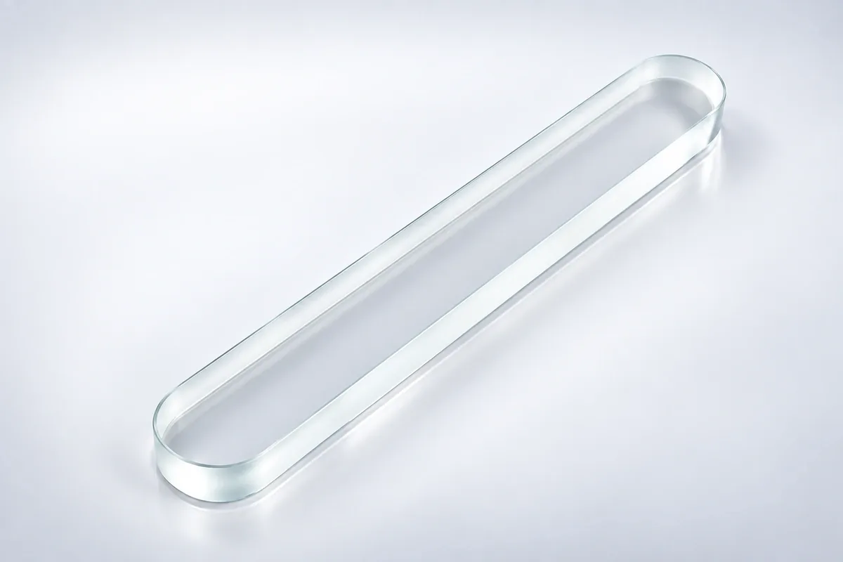
Custom Gauge Glass
Gauge glass is used to indicate the level of liquid in pressurized or non-pressurized vessels, tanks and process columns. The glass works with a gauge body, valves, gaskets and illumination or background to make the liquid interface visible.
The main product families are reflex plates, transparent plates, tubular gauge glass and redline tubes. Each uses a different optical method and must match the controlled gauge housing.
Specification note: Numerical ranges shown on this page are preliminary engineering references for project screening. The quotation and approved drawing define the final material, dimensions, tolerances, processing route and inspection method.
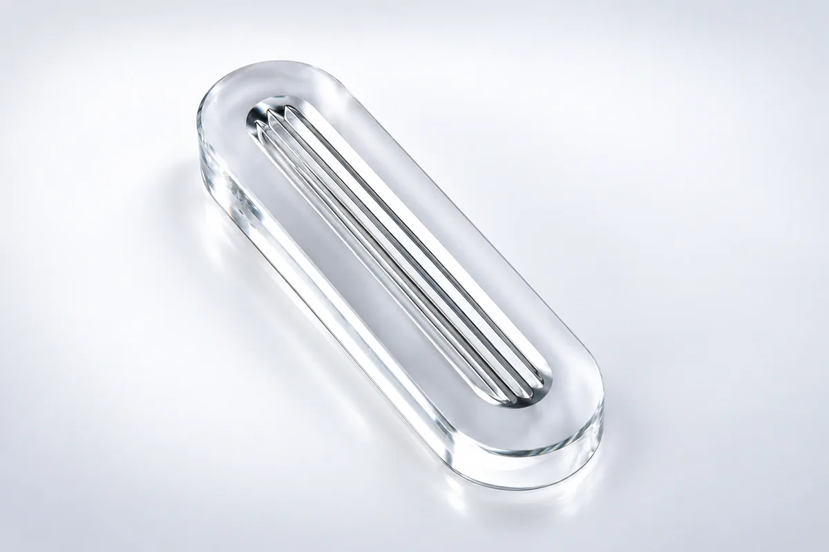
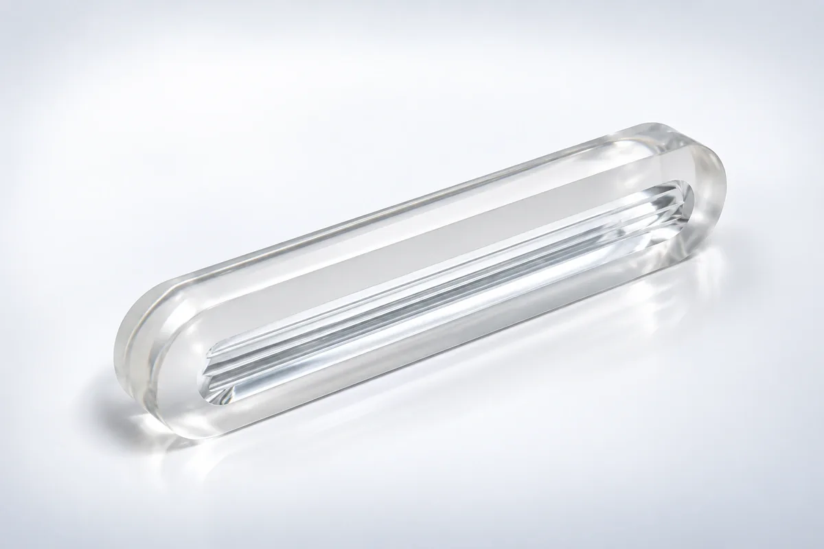
Gauge Glass Types
| Type | Reading principle | Typical arrangement |
|---|---|---|
| Reflex gauge glass | Molded prisms make liquid and vapor regions appear different under reflected light | Single glass plate in a reflex gauge body |
| Transparent gauge glass | Two smooth glasses allow light to pass through the fluid column | Illuminated or backlit gauge body |
| Tubular gauge glass | Liquid level is viewed directly through a transparent tube | Low- and moderate-duty level gauges |
| Redline tube | A colored stripe improves visibility of the liquid meniscus | Boiler and utility level observation |
Gauge Glass Specifications
| Gauge manufacturer / body | Made to the approved drawing; production limit confirmed after tooling review |
|---|---|
| Glass type and material | Selected for the application and confirmed with the quotation and material data |
| Plate length / width / thickness | Common DIN 7081-type sections 30 × 17 or 34 × 17 mm; reference lengths about 95–500 mm |
| Tube OD / ID / length | Not derived from DIN 7081 plate sizes; tubular gauges require a separate drawing and duty review |
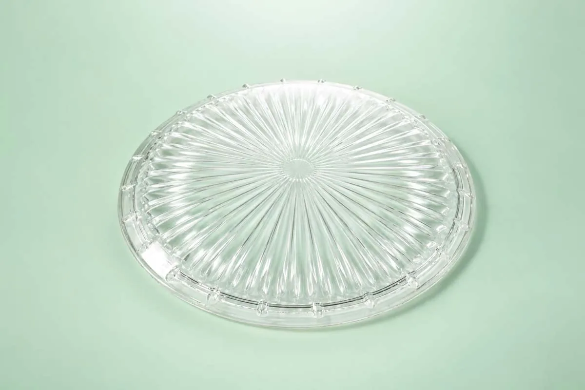
| Prism or face profile | Transparent smooth face or reflex prism profile to the applicable drawing/standard |
| Design pressure | Defined for the intended service environment; assembly-level responsibility agreed before production |
| Continuous / peak temperature | Defined for the intended service environment; assembly-level responsibility agreed before production |
| Process fluid | Defined for the intended service environment; assembly-level responsibility agreed before production |
| Gasket contact and edge | Defined by the gauge-body assembly |
| Applicable standard | DIN 7081 may apply to flat transparent/reflex gauge glass; confirm full scope |
A nominal gauge size may differ between body manufacturers. Final dimensions should come from the controlled gauge drawing or an approved glass and gasket sample.
Reading and Installation
- Prism orientation: reflex grooves must face the correct side of the gauge body
- Transparent pair: front and rear glasses require aligned clear apertures and suitable illumination
- Gasket seating: surfaces must be clean, flat and supported without point contact
- Bolt loading: the gauge maker's tightening sequence and torque govern the assembly
- Thermal conditioning: startup and cooldown must follow the equipment procedure
Component Production Route
Lampoptics can form or process gauge components to a drawing or approved sample, then anneal and inspect the glass. Physical or chemical tempering, coating, sandblasting and drilling are available where the gauge design permits.
Reflex profile, tube size, material, pressure class and test standard are confirmed only after the gauge-body drawing and service duty are reviewed.
Gauge Glass Processing

Gauge Interface Review
Gauge body dimensions, sealing faces, reading direction, pressure and temperature are confirmed.

Blank Forming
The glass is molded or cut to the required flat, reflex, transparent or tubular configuration.

Surface and Edge Finishing
Reading faces, sealing surfaces, edges and any grooves are processed to the drawing.

Reading and Dimensional Inspection
Scale visibility, surface quality, thickness, sealing geometry and fit are inspected before release.
Applications
- Boilers and steam systems: direct liquid-level indication
- Chemical vessels and columns: level monitoring for compatible process fluids
- Storage tanks: local visual level confirmation
- Process skids and utilities: compact reflex or transparent gauge assemblies
- Laboratory and pilot equipment: small tubular level indicators
Gauge Glass FAQs
What is the difference between reflex and transparent gauge glass?
Reflex glass uses prisms and reflected light; transparent gauges use two clear plates and transmitted light through the fluid.
Can one plate fit every gauge body of the same nominal size?
Not necessarily. Length, width, thickness, edge and gasket geometry must match the specific body.
Which side faces the liquid in a reflex gauge?
The prism orientation is determined by the gauge design and controlled installation instructions.
Can Lampoptics reproduce a gauge glass sample?
Yes, provided the gauge body, service duty and applicable standard are also identified.
What Lampoptics gauge ratings are available?
Material, size, pressure class and temperature limit are project-specific and must be tied to the complete gauge assembly.