Custom pressed glass components reach stable production through a sequence of engineering decisions: define the function, review the geometry, select a glass and process, design the mold, approve samples and establish production controls. Skipping directly from a 3D model to a tooling order leaves critical questions about surfaces, tolerances, glass flow, finishing and inspection unresolved.
Key Takeaways
- A complete request combines CAD with service conditions, critical characteristics, quantity and acceptance criteria.
- Design-for-manufacture should occur before the production mold is released.
- First samples validate both the part and the measurement/approval method.
- Change control must connect drawing revision, mold revision, sample approval and production inspection.
Stage 1: Convert the Application into a Controlled Requirement
Describe what the glass does: transmit, diffuse, redirect, protect, display, seal or provide a decorative surface. Add operating temperature, thermal cycling, mechanical loads, chemical exposure and the mating assembly. Mark optical, sealing, mounting and cosmetic zones on the drawing. Quantity and production horizon influence the appropriate tooling and automation strategy.
If an existing sample is the reference, document what may change. Reverse engineering can capture geometry, but it does not reveal the original material, stress history or acceptance standard. The new specification should stand on its own.
Stage 2: Design for Pressing and Mold Release
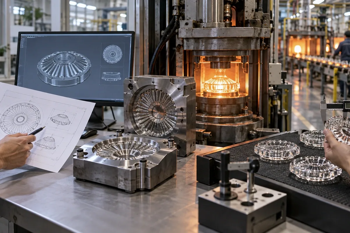
During DFM, engineering reviews draft, radii, thickness transitions, parting line, glass flow, venting, release and post-form trimming. Fine ribs, deep pockets and abrupt bosses may need adjustment. The goal is not to simplify every shape; it is to preserve the functional surfaces while making the part repeatable.
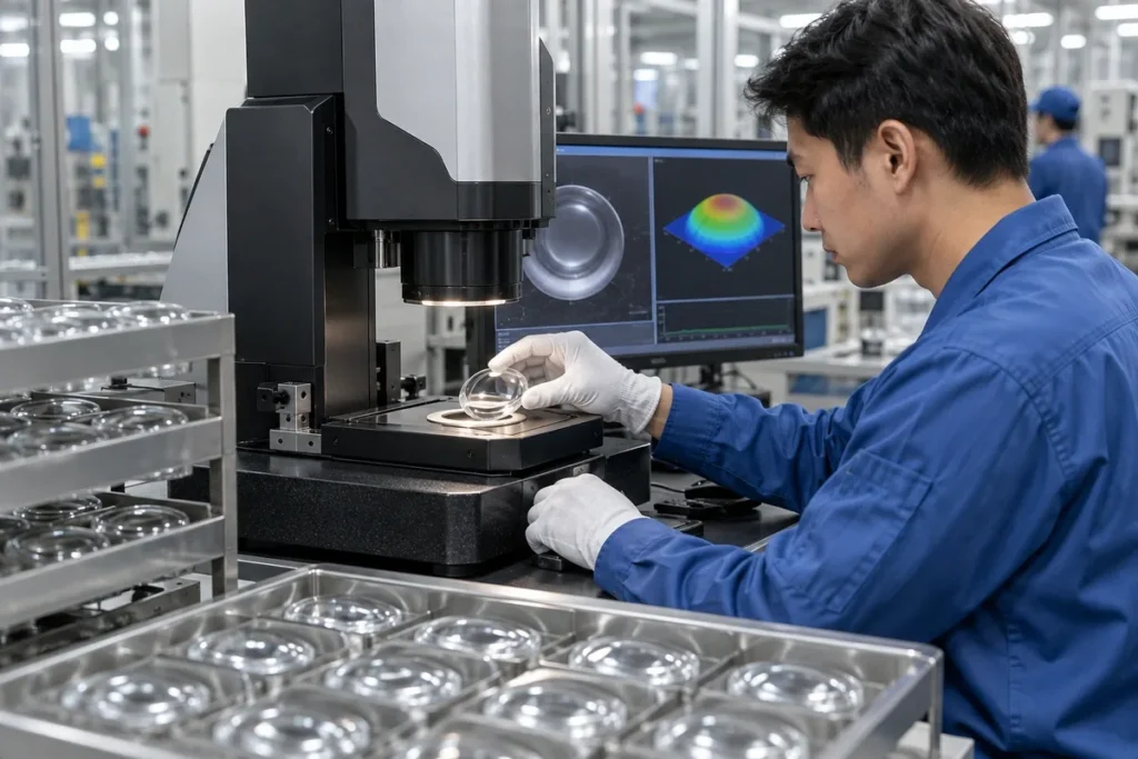
Tolerances are allocated by function. Mounting openings and optical datums may deserve tighter control than the overall decorative envelope. A measurement method should be named for each critical characteristic so that drawing intent can be reproduced at sampling and production.
Stage 3: Select Material, Tooling and Secondary Processes
| Decision gate | Required input | Typical output |
|---|---|---|
| Glass selection | Temperature, optical appearance, media and strength need | Material family and process compatibility review |
| Mold concept | Annual quantity, geometry, finish and critical zones | Parting strategy, cavities, inserts and maintenance plan |
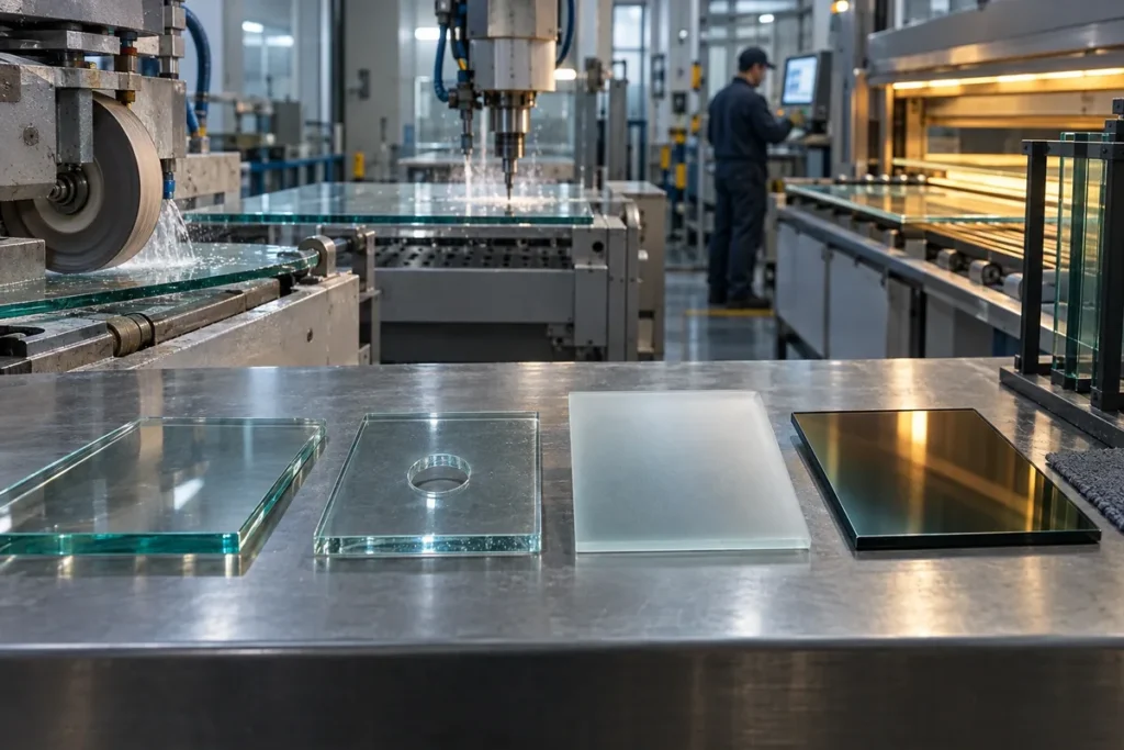
| Secondary processing | Edges, holes, frosting, coating or strengthening request | Operation sequence, masking and feasibility limits |
| Inspection concept | Critical dimensions and performance criteria | Gauges, fixtures, visual standard and test plan |
| Sample approval | Drawing revision and intended assembly | Signed limits, deviation list and production release |
Stage 4: Evaluate First Samples by Function
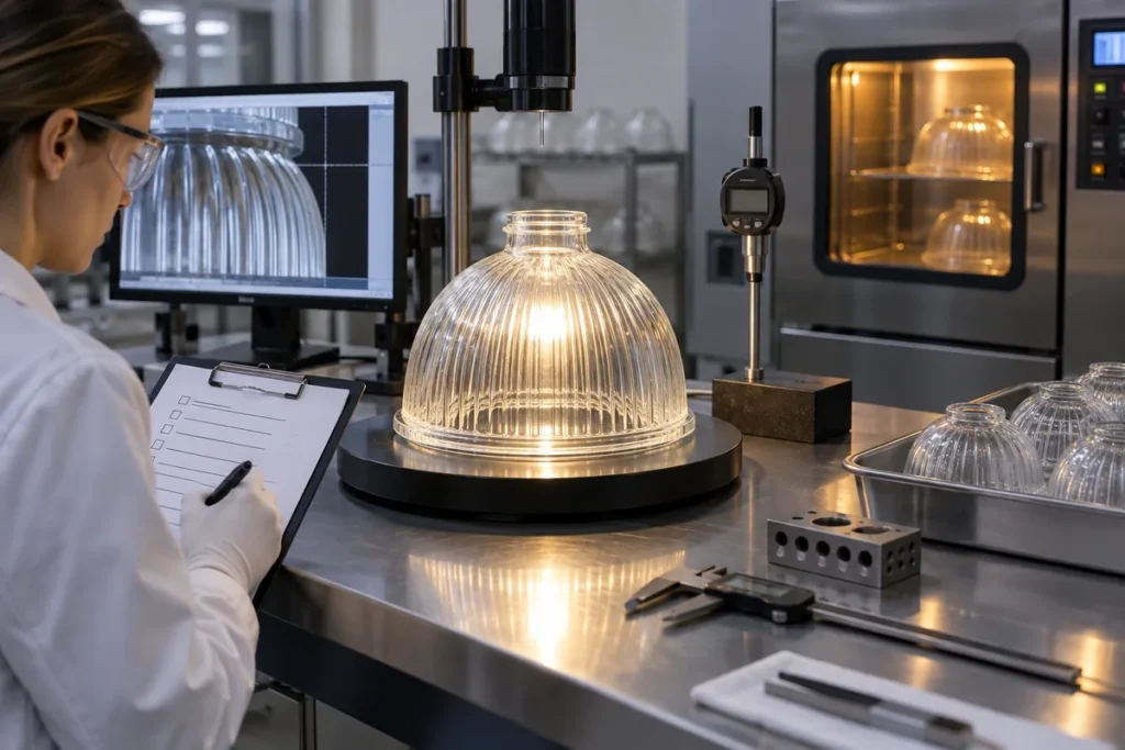
First samples establish more than dimensional capability. Assemble them in the actual holder, illuminate optical parts with the intended source, check sealing faces with the correct gasket and expose thermal parts to the defined cycle. Record acceptable forming evidence and unacceptable defects using photographs or limit samples.
When a sample requires correction, separate mold changes from process adjustments. Update the drawing and approval record so the final production basis is unambiguous. A verbal agreement on an early sample is difficult to reproduce months later.
Stage 5: Build Production and Change Control
Production control focuses on material identity, forming conditions, mold condition, critical dimensions, visual limits and specified functional tests. Sampling frequency should reflect the characteristic and process risk. Tool wear may appear first as flash, loss of texture or fit drift, so preventive maintenance and reference samples are valuable.
Changes to glass, mold inserts, finishing route or inspection method should be reviewed for their effect on the approved product. Traceability does not need to be complicated, but it must connect each shipment with the relevant drawing and production record.
Working with China Lampoptics on a Custom Component
China Lampoptics supports custom pressed glass components from drawing and sample review through mold development, forming and applicable secondary processing. Projects can include lamp shades, molded optical elements and technical glass parts. Each inquiry is reviewed against the real geometry and performance requirement.
Send 2D and 3D files, application conditions, material or appearance target, critical tolerances, test requirements, prototype quantity and annual demand. Where a value is not yet known, mark it as an open item so it can be resolved during engineering review instead of being replaced by an unsupported assumption.
Watch: A Related Glass or Optics Process
Corning's video depicts a different forming technology, but it clearly shows the relationship between molten-glass condition, controlled tooling and consistent output that applies across glass manufacturing.
Related Products and Capabilities
Continue Reading
Discuss Your Custom Pressed Glass Components Project
Send your drawing, application conditions, quantity and the characteristics that matter most. China Lampoptics will review the information and identify the open technical items before quotation.
Contact China Lampoptics