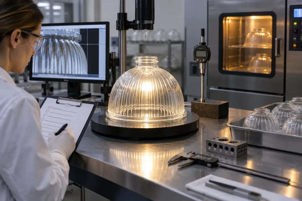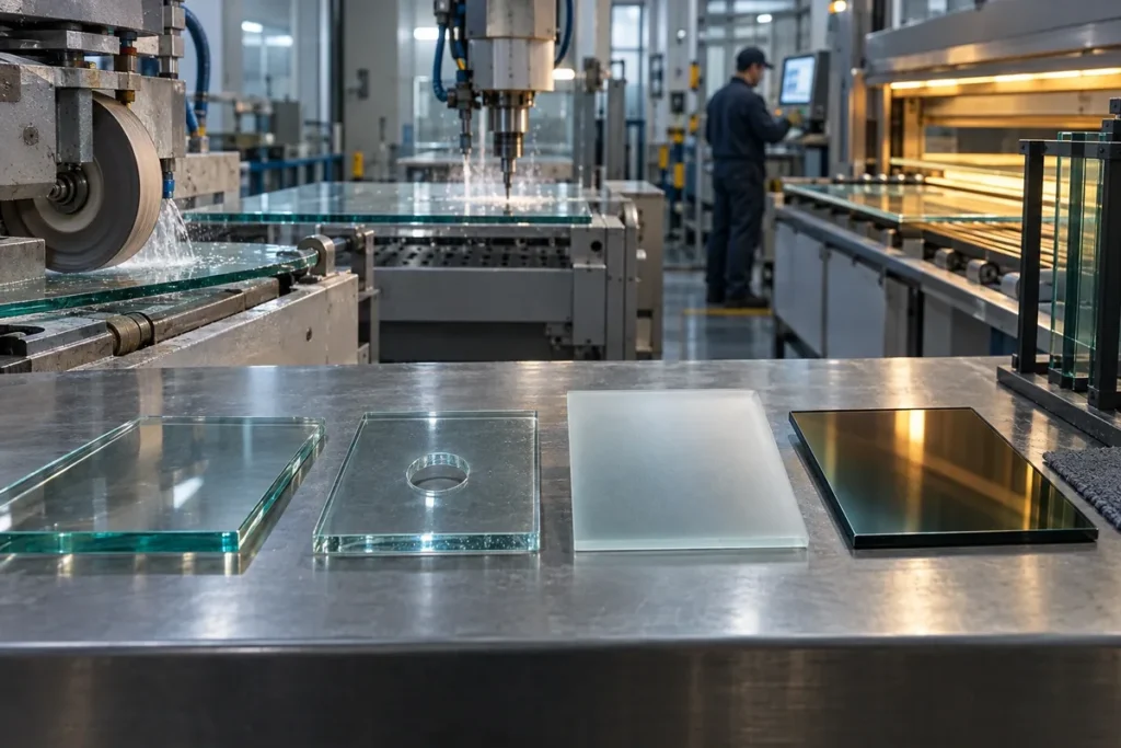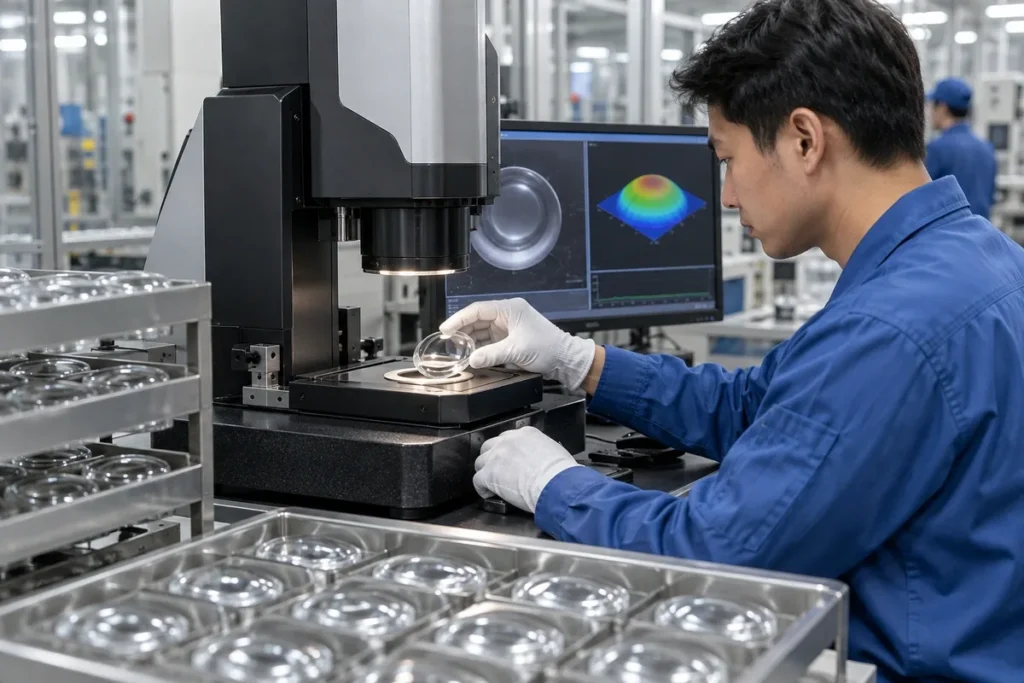
Fly-eye glass lens arrays improve illumination uniformity by dividing light into many beamlets and recombining them at a target or pupil. They are used when a lamp, LED cluster or arc source produces a non-uniform field that downstream optics cannot tolerate. Performance depends on the whole homogenizer layout, especially lenslet pitch, focal length, array spacing, source etendue and alignment.
Key Takeaways
- A single lenslet array segments the beam; paired arrays provide stronger field homogenization.
- Lenslet pitch and focal length must match the condenser, target size and system aperture.
- Source size and angular spread set a physical limit on attainable uniformity and efficiency.
- Mold replication, array alignment and edge treatment are part of the optical design.
How Does a Fly-Eye Homogenizer Work?
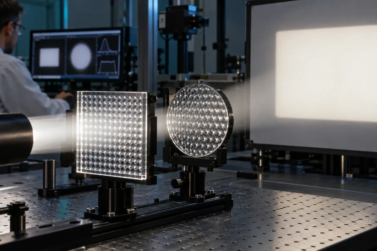
Each lenslet samples a different portion of the incoming field. In a common two-array arrangement, the first array creates multiple source images and the second redirects the corresponding bundles. A condenser then overlaps those bundles at the illumination plane. Bright and dark regions from the source are averaged because each target region receives contributions from many channels.
The name “fly-eye” describes the repeated cellular appearance, not one fixed prescription. Arrays may be square, rectangular, hexagonal or application-specific. Lenslets can be spherical, aspherical or freeform, and the pitch may differ in the two axes to create a rectangular field.
Key Parameters for Glass Lens Arrays
| Parameter | Optical role | Manufacturing or assembly concern |
|---|---|---|
| Lenslet pitch | Sets channel spacing and contributes to field structure | Replication uniformity and array-to-array registration |
| Lenslet focal length | Controls source imaging and system spacing | Surface sag, index and form accuracy |
| Clear aperture / fill factor | Influences throughput and inactive boundaries | Edge radii, seams and mold transitions |
| Array spacing | Determines how paired arrays exchange ray bundles | Spacer tolerance, thermal shift and tilt |
| Array orientation | Sets field axes and channel registration | Mechanical keying and visible alignment marks |
Uniformity, Efficiency and Etendue
Uniformity cannot be improved without respecting conservation of etendue. A wide, extended source occupies both area and angle; a passive optic cannot compress both arbitrarily. Designers trade target size, numerical aperture, efficiency and smoothness. Increasing the number of lenslets may reduce visible structure, but smaller features become harder to replicate and more sensitive to surface errors.
Define how uniformity will be calculated: minimum-to-maximum ratio, RMS variation, a cropped measurement area or another agreed metric. Also specify wavelength range, working distance and detector resolution. Otherwise, two teams can measure the same field and report different answers.
Designing a Molded Array for Production
Molded glass can serve high-temperature or durable illumination systems, but the array must be designed for fill, release and cooling. Lenslet valleys and edge transitions need feasible radii and draft. The mounting border should provide datums without clipping active lenslets. If two arrays are used, the housing should control axial spacing, lateral shift and rotation.
Inspection can combine dimensional sampling, surface comparison and a functional homogenization test. A master image or reference beam map is often useful for production comparison. The system test should include the intended source because a smooth laboratory collimated beam can hide behavior that appears with the real LED or lamp.
Custom Fly-Eye and Lens Array Support
China Lampoptics reviews molded glass lens-array projects for geometry, tooling and repeatable assembly. Customers may provide an optical prescription, a STEP model plus performance target, or a physical reference part. Engineering review identifies the optical surfaces, mounting datums and inspection approach that must remain connected through production.
For early-stage designs, begin with the illumination requirement rather than a copied pitch value. This allows the array architecture and surrounding condenser optics to be developed as a system.
Watch: A Related Glass or Optics Process
This Edmund Optics demonstration offers a visual refresher on how lenses redirect bundles of rays. Fly-eye systems extend that logic by repeating many small lenses across an array.
Related Products and Capabilities
Continue Reading
Discuss Your Fly-Eye Glass Lens Arrays Project
Send your drawing, application conditions, quantity and the characteristics that matter most. China Lampoptics will review the information and identify the open technical items before quotation.
Contact China Lampoptics