Molded glass lenses control LED light distribution by redirecting rays at one or more curved, faceted or textured surfaces. The resulting beam is determined by the complete optical system: LED emitting area, source position, refractive index, lens geometry, surface quality and any reflector or cover around it. A lens copied from another luminaire rarely produces the same result when those conditions change.
Key Takeaways
- Define the target intensity distribution before choosing a lens shape.
- Treat LED package size and lens-to-source position as controlled optical dimensions.
- Use molded texture for redistribution or mixing only when its optical effect is understood.
- Approve performance with photometric or application-level testing, not appearance alone.
How Does a Molded Glass Lens Redirect LED Rays?
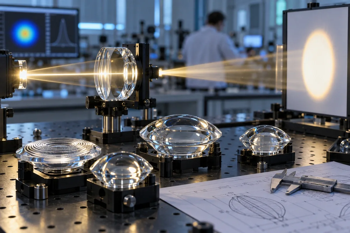
When light crosses an interface between air and glass, its direction changes according to the refractive indices and surface angle. A convex entrance or exit surface can converge rays; a concave surface can spread them. Steeper internal surfaces may use total internal reflection to redirect light with little dependence on a metallic coating. Molded ribs and prisms divide the surface into many local optical elements.
Real LEDs are extended sources rather than mathematical points. Rays leave different positions across the die or phosphor area and at different angles. The closer the optic sits to the source, the more strongly small assembly shifts can change the beam. Optical simulation should therefore use the actual LED ray set and mechanical stack-up.
Match the Lens Architecture to the Required Beam
| Lens approach | Useful for | Main design sensitivity |
|---|---|---|
| Plano-convex or bi-convex form | Convergence, imaging or simple beam control | Curvature, thickness, refractive index and source distance |
| Aspherical surface | Reducing selected aberrations or improving compact beam control | Surface prescription and manufacturing fidelity |
| Prismatic or ribbed surface | Spreading, redirecting or breaking up visible source images | Facet angle, pitch, orientation and tooling release |
| TIR-style optic | Compact collection and controlled output | LED centering, air gaps and internal surface geometry |
| Lens array | Beam segmentation, mixing or uniform illumination | Lenslet pitch, pair spacing and alignment |
Which Inputs Belong in an Optical Lens Specification?
Start with the target beam: angular distribution, center intensity, field angle, cutoff, uniformity and allowed stray light. Add the LED manufacturer and part number, nominal flux, emitting-area dimensions, spectrum and operating temperature. Define the lens coordinate system, reference surfaces, mechanical clearances and allowable source displacement.
The drawing should distinguish optical surfaces from mounting and cosmetic surfaces. Surface form, waviness, roughness, bubbles, inclusions and molded flow evidence affect different applications differently. A non-imaging lamp optic usually needs a different acceptance method from an imaging lens, so do not import an imaging specification without justification.
Design for Glass Molding and Repeatable Assembly
Glass molding adds draft, fill, cooling and release considerations to the optical prescription. Very sharp features may not fill consistently; abrupt thickness changes may cool unevenly; a parting line may interrupt a functional surface. The optical designer and mold engineer should agree which geometry can change without losing the beam target.
Mechanical design then has to hold the LED and lens in the simulated relationship. Use locating features that reference the optical axis, avoid uncontrolled adhesive thickness in critical gaps, and provide room for thermal expansion. A high-performing nominal design can fail in production if centering and height tolerances are not allocated through the assembly.
Custom Molded Glass Lens Development
China Lampoptics supports drawing and sample review for molded glass lenses, including manufacturability feedback, mold development and process planning for appropriate finishing and inspection. For a new LED optic, provide the ray file or complete source data, target distribution, mechanical envelope, material preference and expected volume.
Where the performance target is not fully defined, an existing reference optic and comparative beam requirement can establish a starting point. Final optical performance remains dependent on the customer's LED, housing and assembly, so validation should use the intended system.
Watch: A Related Glass or Optics Process
This Edmund Optics demonstration provides a concise visual explanation of refraction and total internal reflection, the two principles behind many molded beam-control surfaces.
Related Products and Capabilities
Continue Reading
Discuss Your Molded Glass Lenses Project
Send your drawing, application conditions, quantity and the characteristics that matter most. China Lampoptics will review the information and identify the open technical items before quotation.
Contact China Lampoptics